Assembling the Pi-Repeater-2x Case
If you bought the cased system or have decided to add the case to protect your repeater controller after having setup the basics, this guide will show you the correct way to assemble your case. Depending on the state of your assembly, you can jump ahead to the appropriate state to complete the process. Most likely this begins at step 7.
Step 1: Prepare your cables
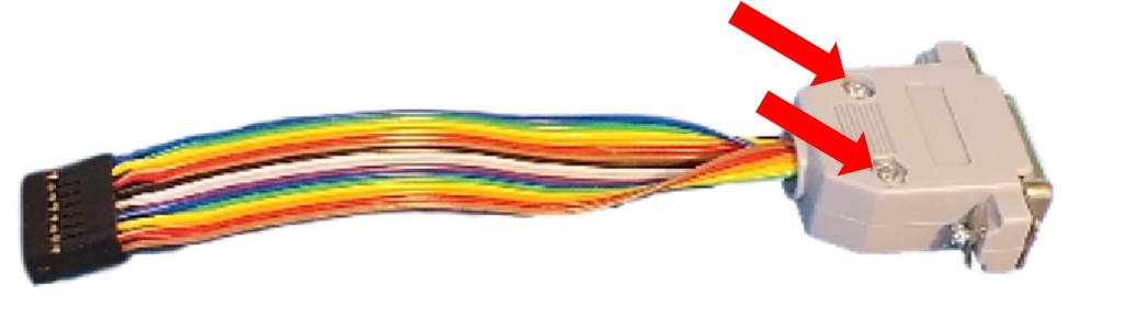
Begin preparing you cables by removing the protective cover blocks by removing the two indicated screws. Under the cover is an additional cable clamp that acts as a strain relief that should be removed as well.
You should do this for all 4 of the DSUB cables. Keep these connector covers to use on your radio interface cables if building your own cables.
Step 2: Prepare the USB power supply
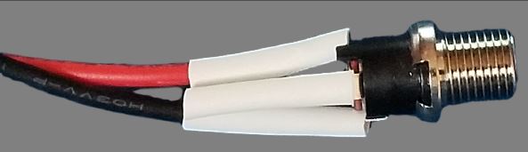
Gather up the power converter, the power receptacle and 3 pieces of shrink tube about 0.5 Inches long, anything sufficient to cover the soldering tabs is sufficient.
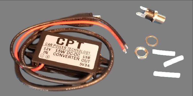
Slide the shrink tubing onto the red and black wires of the power converter, keeping them far enough away from the exposed wire to not shrink during soldering.
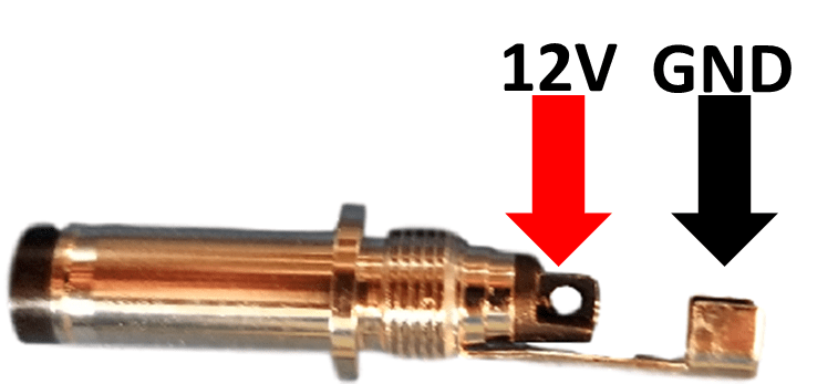
Solder the red wire onto the tab that visibly connects to the center rivet. This is the center pin of the receptacle and should be the 12V wire.
Solder the black wire to the tab that is 180 degrees across the connector.
Slide the shrink tubing down from both wires all the way to fully cover the soldering tabs of the connector. Add the 3rd piece of shrink tubing over the unused terminal and shrink all 3 pieces down tight to insulate these terminals from accidentally touching the case once installed.
Once assembled set aside temporarily.
Step 3: Install the DSUB cables in the case
This is one of those processes that feels like it would be easier with 3-4 hands to hold everything. Take your time and be patient, it will all work out. If you get frustrated, call CQ a couple times and come back to it, even we sometimes need a break from this part of the assembly, its OKAY :-).
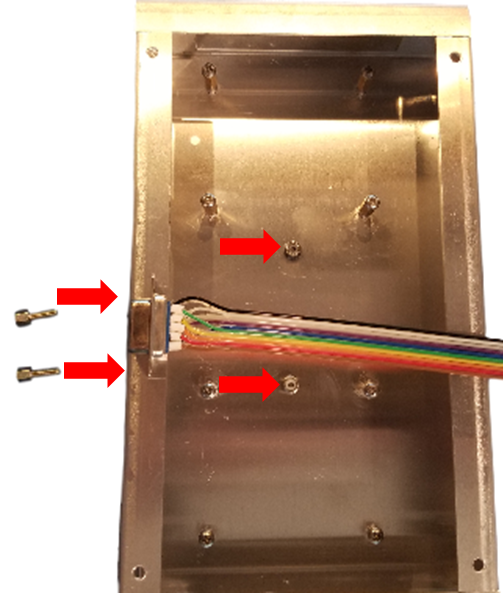
Install the 4 DSUB cables into the front of the case using the 8 Jack-Screws and 8 4-40 nylon Lock nuts provided. The clearance is tight inside next to the DSUB connector frame. Be sure all PCBAs are completely removed from the case if you are working on a previously assembled case, a tool slip will easily damage one of the PCBA.
Suggested approach is to tape the tail such that it will help to hold the connector against the face. A strong magnet on the front face outside the box can also help to hold the connector in place.
Having the connector in place, insert the Jack-Screw and get the nylon lock nut threaded on until its finger tight. Then repeat for the second jack-screw and nut. We suggest tightening the nut while not rotating the jack-screw, but there isn’t any harm if its easier to anchor the nut (with a flat head screw driver perhaps <hint>) and then tightening the Jack-screw instead. Be sure to go slowly to not break the Jack-Screw, these are brass and will break easily when force is applied and the nut is already tight.
Phew, glad that step is done, we promise it gets easier from here.
Step 4: Install the Power Supply
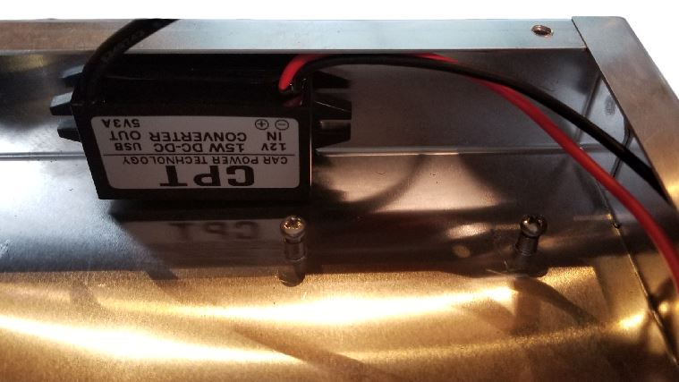
With the assembled power supply in hand, find the velcro square and apply one side to the back of the power supply unit. We typically leave the velcro pieces attached for now.
Having the velcro in place, install the power connector into the case, with the washer and nut on the outside of the case. We suggest lightly tightening the nut, but finger tight can be sufficient if you have strong fingers.
With the connector fully in place, apply the block with the velco to the back of the case. To allow access to the microSD card after installing the Pi, we suggest making sure the body is aligned or outside the pinch nuts.
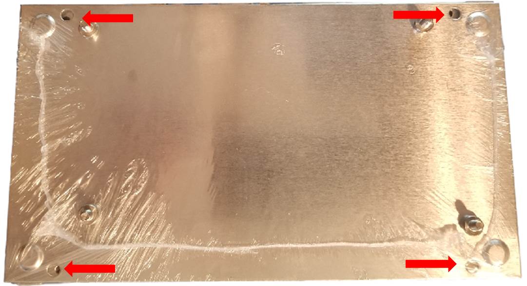
Step 5: Installing the Pi-Repeater-2x Controller Card
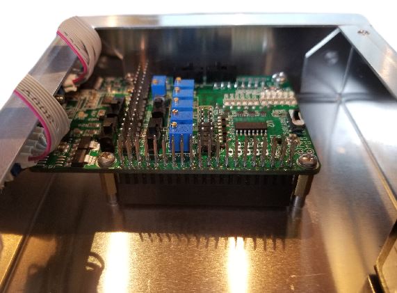
Install the Pi-Repeater-2x card onto the Pinch Nuts behind the DSUB-15 connector. You will need to use the QTY 4, M3 stand-offs to raise the threads up enough to accommodate the stacking connector on the controller board.
Cables should be folded out of the way to make this step a little easier. Tweezers are helpful for holding and placing the screws into the 2 spots closest to the back narrow side of the case.
As these screws and stand-offs are part of the chassis ground connections, ensure the threads are all snug, but don’t over-tighten or the any of the threaded pieces may break, including the pinch nuts breaking free of the case. This is soft aluminum and brass, not automotive grade steel.
Step 6: Installing the Raspberry Pi Computer
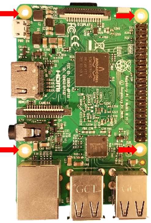
The holes in the raspberry pi will need to be opened up slightly to allow the M3 screws to fit through. The Raspberry Pi boards have 2.9mm diameter rather that something standard and useful. This was intentional so the Raspberry Pi foundation claims. Anyways, the fiberglass is not masked in the area where it is safe to work, but don’t go crazy, it only take a little bit more diameter to make it all work.
Due to the intentionally snug fit of the USB and Ethernet connectors to the front of the case, the assembly process needs to be followed carefully to ensure you don’t damage the Raspberry Pi Computer board.
6.1: Insert the connectors top lip through the opening.
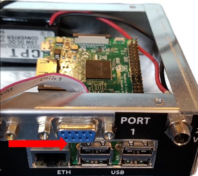
Holding the board inside the case at about a 30 degree angle, slide the Pi USB connector tops through the opening in the front of the case. Pay attention to the pinch nuts inside the case so you don’t break any of the components off the bottom of the Pi board.
6.2: Seat the connectors in the opening
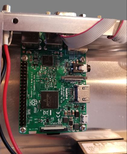
Wile maintaining the angle, raise the entire board up to the top of the opening and then gently rotate the board so the connectors fully come through the opening. Once the connectors are fully seated through the opening, then you can proceed to putting in the screws
6.3: Install the Pi Screws 50% depth
Install the screws each only 50% depth until all 4 are installed. Like the lug-nuts on your tires, you want to make sure the screws are all started before you tighten them down or you may need to take them back out and try again.
Be extremely careful to not cross thread these screws, if they cross thread, there is a very high likely-hood you will need to drill out the nuts and break off the screw to get it loose. We order these cases prefabricated, we cannot help you to repair the damage should this occur.
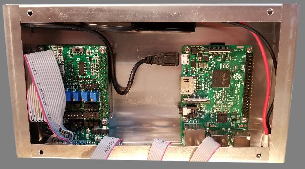
Step 7: Hooking up the cables
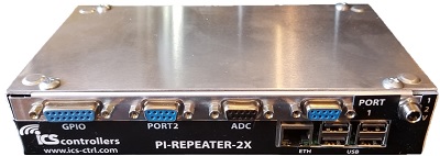
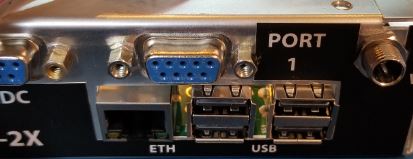
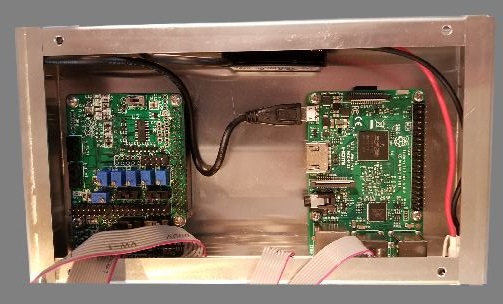
At this stage, you should have a case that looks like the figure here, assuming you have made it this far successfully, the last steps are to hook up the cables to the controller board, put the lid on, and build a power cable
7.1: Hook up Port 1 cable
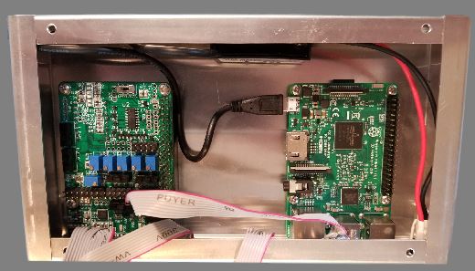
Note the orientation of Pin 1 (Red wire) in the cable as connected.
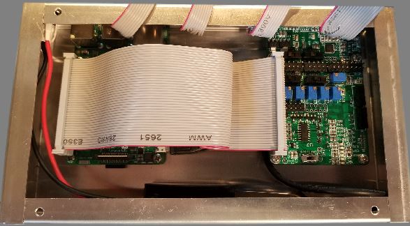
7.2: Hook up ADC cable
Note the orientation of Pin 1 (Red wire) in the cable as connected.
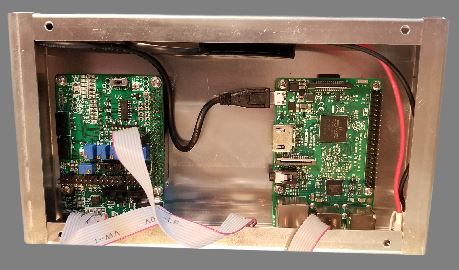
7.3: Hook up Port 2 cable
Note the orientation of Pin 1 (Red wire) in the cable as connected.
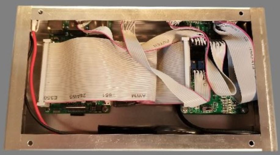
7.4: Hook up GPIO cable
Note the orientation of Pin 1 (Red wire) in the cable as connected.
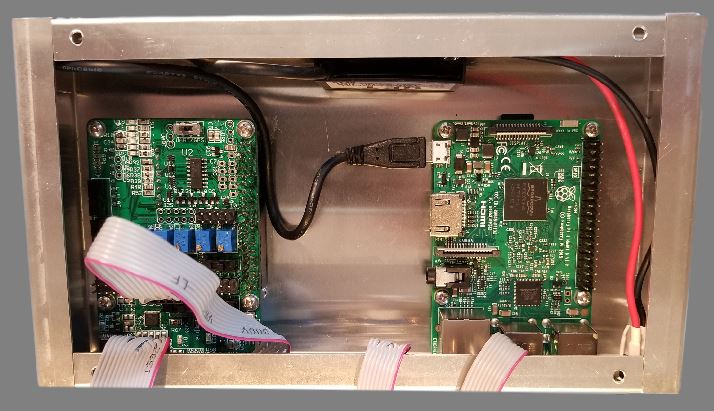
Step 8: Install the 40 Pin Ribbon Cable
Note the orientation of Pin 1 (Red wire) in the cable as connected.
Step 9: Install the Lid using #8-32 x 3/8 Screws
Step 10: Build a power cable
Using the connector provided, make a 12V power cable. If you need a replacement connector, you can pick one up from Digikey