Issue – Audio output adjustments are very sensitive (less than 2 turns min to max volume)
Typically this is caused by the output levels being set very high in either ALSAMIXER, or the sensitivity of the mic input in your radio are set too high. When set correctly, there should be many turns of the output potentiometer required to go from low audio level, to audibly detectactable clipping.
Issue – No audio Input or output
NOTE – The images and content shown below are specific to the Version 3.xx of the PI-REPEATER-2X interface adapter board. The Version 4.xx and higher (if available in the future) has a revised schematic. Reference the schematics on our documents page and the user manual for applicable test points.
If after going thru these steps you are stuck, please contact us for further guidance.
Tools you will need
- 40 pin IDC ribbon cable 6+ Inches (to allow probing the bottom side of the controller board). If you have our cased system, the included one is sufficient
- PC – linux/Mac/Windows with terminal program such as PuTTY
- Oscilloscope – basic unit capable of measuring 5V and 100KHz sine wave
Preparing the software environment (in SSH or console)
Run the following commands to disable svxlink and put the audio system into a tone generator mode that will output 500 Hz that will alternate between the 2 audio channels in the codec chipset. Note that you should monitor each node for about 5 seconds to ensure you don’t miss diagnose a mode when the unused channel is being activated.
sudo alsamixer
When the alsamixer utility loads, inspect the audio card, this should report as “FE-PI”. Next inspect the volume levels and configurations. The audio input (MIC) should be set to “LINE-IN” and output should be set to “DAC”.
If any settings are adjusted, issue the command sudo reboot after exiting. Failure to reboot will cause the settings to be lost if power is reset.
sudo service svxlink stop
This will disable the svxlink application so the audio card can be used for debugging.
sudo speaker-test –c 2 –t sine –f 500
This will set the audio chip to output a sine wave signal that alternates between the two audio channels available. Note, only 1 channel is used in this controller board.
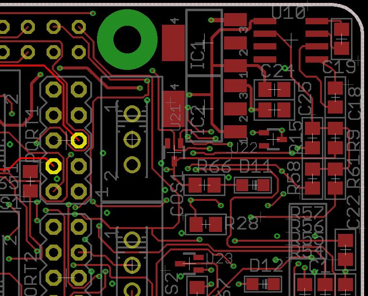
AUDIO OUTPUT PORT 1
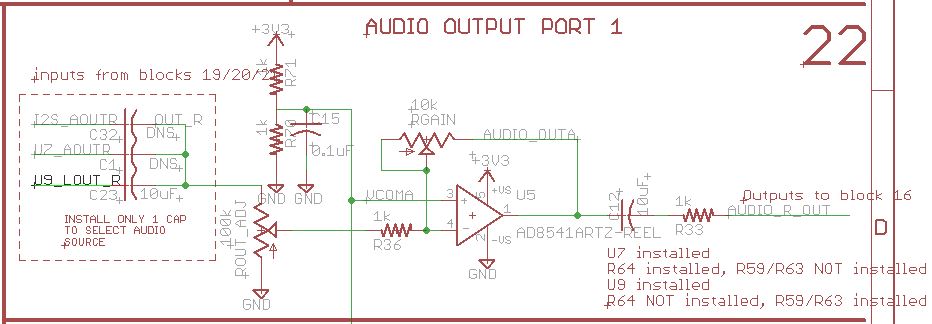
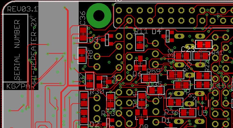
Probe each side of C23
A sine wave of 500 Hz should be measured, the amplitude of the signal is controlled by the software volume setting in “alsamixer” utility. Ideally this signal should be approximately 1V to have good signal strength while preventing distortion.
Probe each side of R36
The left side of R36 is the audio output after the ROUT adjustment potentiometer which should be used to adjust the final output volume. This voltage should be adjusted using the ROUT_ADJ potentiometer to approximately 0.25Vpp to begin with.

The right side of R36 is a combination of the input and feedback from the amplifier. If no signal is detected here, slowly adjust the RGAIN potentiometer until a maximal non-distorted signal is measured. If you are unable to get any signal on the right side of R36, U5 may be defective and shorting the signal to ground.
NOTE: Not show is the amplifier IC U5 stage, if R36 has signal on the right side, the input to this pin will also be good which originates at U5. If the C12 (next step) has signal, the U5 amplifier stage is working properly.
Probe each side of C12
C12 is a DC blocking capacitor and should not impact signal levels. If signal is present on one side of C12, but not the other, then either C12 or U5 is defective and needs replaced.
Probe each side of R33
R33 is a damping resistor to help prevent oscillations and noise in the wiring and should not impact signal levels.
Check the Tx Audio header pin
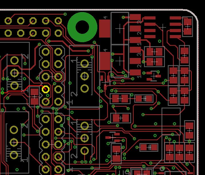
If you have made it this far, the Channel 1 Tx Audio path has been checked for functionality.
AUDIO INPUT PORT 1
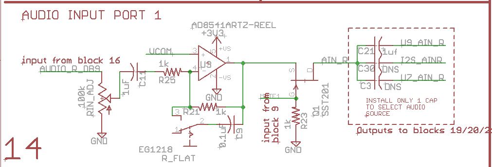
Jumper Output to Input
To get started with trouble shooting received audio, first step complete the above process for enabling a sine wave from the audio chip. Then jumper the Rx Audio to the Tx Audio signals. You can do this either right on the 2×5 header, or in a DSUB-9 connector depending on what is most convenient
Probe each side of C11
Probe the top side of C11 to check the output of the RIN-ADJ potentiometer. The bottom side of C11 is the DC blocker that feeds the Flat Audio amplifier input.
Probe each side of R25
R25 is the input stage of the Flat Audio; depending on the setting of the switch, the scale of the output side may vary, but the signal should still be present.
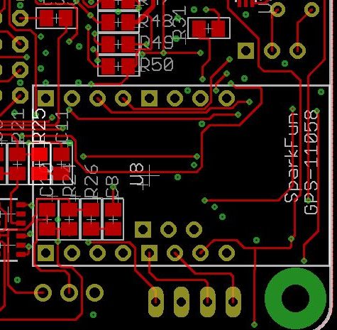
Probe each side of Q1 (0 OHM Resistor)
Q1 is the output stage of the Flat Audio amplifier circuit, signal should be equivalent on both sides of the resistor
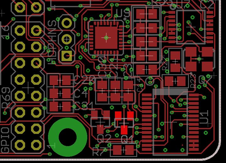
Probe each side of C21
C21 is the last component before the audio enters into the audio chip. The audio should be unaffected by passing through this component except DC voltage blocking.
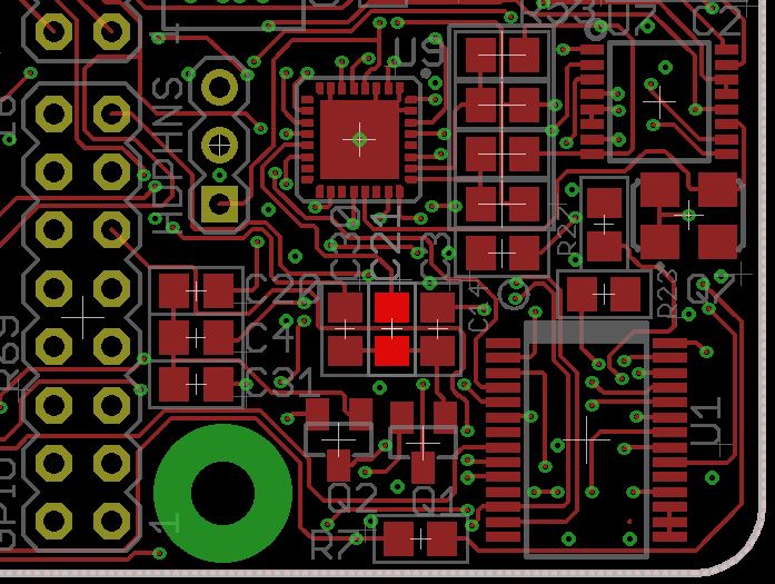
If you have traced the CH 1 audio to this point, the only possible remaining point of failure could be the audio chip input pin. This can be tested by recording the audio input to file and then playing it back out the output.