DISCLAIMER: We at ICS-CTRL have no direct experience with the MTR2000 equipment, we will not be able to support implementation questions that are specific to the MTR2000. We of course will support questions directly related to the usage of our product at a functional level and its operation.
We cannot be held responsible for any misprogramming of your station that may render it unusable. You follow these directions at your own direct risk of equipment damage and cost for repair and replacement.
From the experience of our beta testers, getting the MTR2000 fully up and running can be quite the challenge to get all the configurations correct. From their efforts along the way, we have collected a number of tidbits that may help you get up and running. If you have content to contribute to this page to help others, we will be happy to accept suggestions to include for others. You can remain anonymous or take credit for the work at your own discretion, just let us know when you tell us what we should consider including.
Alright, now that is out of the way, lets get to the integration shall we?
STEP 1: UPDATE THE MTR2000 FIRMWARE
The very first thing we recommend you to do is contact Motorola and get the latest firmware for the MTR2000 radio. Most of the radios on the ham market have obsolete software that has known issues that may hinder your integration attempts. This can take a while to get back from Motorola so ask this first before you start anything else.
STEP 2: Make sure you have the latest version of Open Repeater software installed on your micro SD card.
Visit https://openrepeater.com/downloads to grab the latest image available. While the zero is not officially supported, the image will work on the zero, but you may need to make some minor adjustments to things like GPIO pin numbers or such to get it all working.
Now that the image has been downloaded and unzipped, it is time to write it to your micro SD card. We suggest to follow the current instructions from open repeater as well to make sure you do it per the needs. You can find the instructions here: https://openrepeater.com/getting-started
STEP 3: Configure Wireless Networking
Create a file on the boot folder (the top level folder of the drive under windows) using notepad / notepad++ or similar text editor, do not use ms word for this. Use the file name “wpa_supplicant.conf”. Place the following information in the file to allow the pi to self configure the wireless network on the next boot.
ctrl_interface=DIR=/var/run/wpa_supplicant GROUP=netdev
update_config=1
country=us

network={
    ssid="NetworkID"
    psk="PASSWORD"
    priority=1
}
If you are having problems getting this to work, we recommend moving the SD card from the PI Zero to a regular raspberry pi and logging in via SSH and configuring the wireless using the raspi-config utility. Once the configuration is completed, exit the raspi-config utility, wait about 15 seconds and issue the command ifconfig. Look at the bottom of the report for the wlan and make sure it has an IP address. This is the confimation that the settings are correct and the system is able to connect to the router.
From here move the sd card back to the PI zero.
STEP 4: Boot the Pi and locate it on the network
Remove the micro SD card from your computer and install it in the pi-repeater-1x-mtr2000 controller.
Hook up the controller to your MTR2000, the controller will receive power directly from the radio. It is recommended to have the setup as close as possible to the wireless router during this process as there is a lot of metal near the wifi antenna that can interfere with the ability to connect to the router. You want as strong of a signal as possible.
Now that the controller and radio are powered on, you will need to locate the controller’s IP address on your router’s IP table, or using a tool such as Angry IP Scanner.
STEP 5: Log into the Open Repeater User Interface (UI) and configure the software.
Start here: https://openrepeater.com/getting-started#5d86380f7ab63 and follow the process through the rest of the instructions page. You will select the PI-REPEATER-1X in the wizard page. The wizard will configure the rest for you to get the basics setup.
NOTE1: With the introduction of Buster OS image, gpio numbering assigned to the GPIO expander used for PTT signals has changed unexpectedly, and the change is not universal between all versions of the RPI. As a result, you may need to reduce the gpio numbers above 400 in the open repeater configuration menu for version 2.1.2 by -8, so gpio506 would become gpio498 as an example.
NOTE2: We have heard that some radios are not quite able to toggle the active low GPIO interface. There is a workaround for this situation that can be viewed here: https://ics-ctrl.com/active-low-work-around/
Configuring the MTR2000
Disclaimer again, you are on your own for this part. We have no radios or knowledge of them to assist you. We cannot guarantee any of this information is correct, or appropriate for your specific radio configurations. These are just examples for what has been shown to work with this user’s particular setup.
Keep in mind as you proceed forward that it is well known that the MTR2000 code-plugs can suffer from corruption when readout and reloaded multiple times. We suggest to start from scratch to prevent unnecessary heartache from code-plug rot.
CONNECTING UP THE AUDIO
There are 2 ways of interfacing the audio to the controller.
(1) A jumper between pins 2 & 3 and a jumper between pins 4 & 5 on the PI-REPEATER-1X-MTR2000 adapter board J3 (Note this silk screen is missing, the connector is immediately adjacent to J4). Unfortunately, this method does not pass PL properly. Using this method, the MTR2000 will only pass PL or DPL when an appropriate PL tone/DPL signal is received.
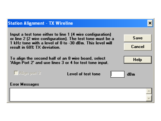
(2) Use the wireline connector on the repeater (tone remote control board required)
Construct a shielded cable interface utilizing either J3 (5 pin header on the controller board) or J2 (DB-9F) on the control board and the Wireline Connector (J6 on the MTR2000). Note that there is no matching connector (plug?) for the Motorola MTR2000 chassis mounted wireline connector.
Bare or stranded wires are inserted in the round holes in the connector. If you use stranded wire for the connections, be sure to tin the wires first to avoid shorts. The rectangular holes above each round hole are to release the wires after they have been seated. Use a very small, slotted screwdriver or other appropriate tool with a fine point, a strong paperclip has also been shown to work well.
Audio from the controller to the transmitter: Wireline Audio In goes to the controller Audio Out
Audio from the receiver to the controller: Wireline Audio Out goes to the controller Audio In
| MTR Wireline Connector (J6) Function -> Pin | ICS Interface Board (DB-9F) Pin # -> Function |
| Receive Audio (-) -> -1 | 6 -> Tx Audio Ground |
| Receive Audio (+) – > +1 | 4 -> Tx Audio |
| Transmit Audio (-) -> -2 | 8 -> Rx Audio Ground |
| Transmit Audio (+) -> +2 | 5 -> Rx Audio |
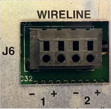
J6 Wire Line Terminals 1-4:
The connector accepts solid wire or stranded wire that’s been twisted and tinned. There is NO mating connector. The wires get inserted into the round holes. To release the wires, insert a round tool, a small nail, or another wire into the rectangular hole above the wire. Motorola also sells a Wireline Connector Tool just for this purpose: p/n 6600809D00.
http://www.repeater-builder.com/motorola/mtr2k/rear-panel/backplane-pins.html
The MTR2000 Depot Service Manual 6881096E35 contains the
admonition that any signal to the auxiliary audio input (pin A17)
MUST be AC-coupled through a 100 uF electrolytic capacitor. Failure
to have this capacitor in line will upset the bias on op-amp U4509,
which is DC-coupled to the backplane connector. Some controllers
have DC-coupled or transformer outputs, and may not work properly
without this capacitor. In fact, you’d be wise to use a similar
capacitor (with the positive end pointing towards the station) for
any and all audio signals to and from the station.
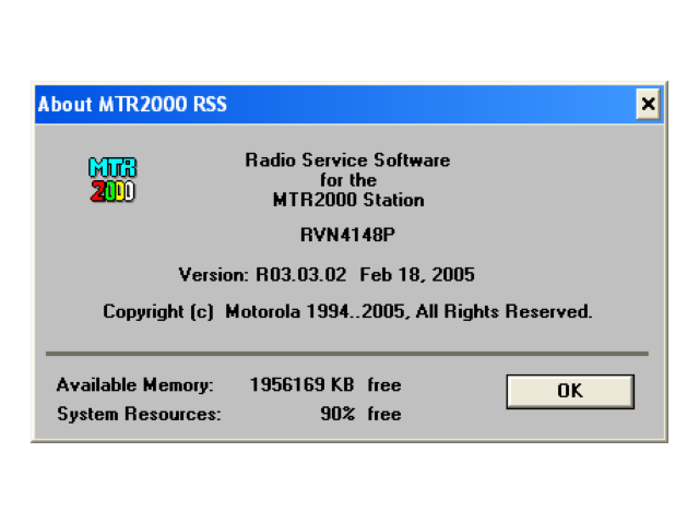
The current RSS for the MTR2000 is RVN4148P, version R03.03.02 and is not backward-compatible.
http://www.repeater-builder.com/motorola/mtr2k/mtr2000-followup.html
Eric Lemmon WB6FLY
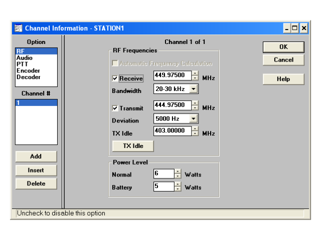
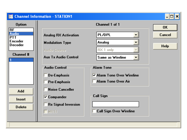
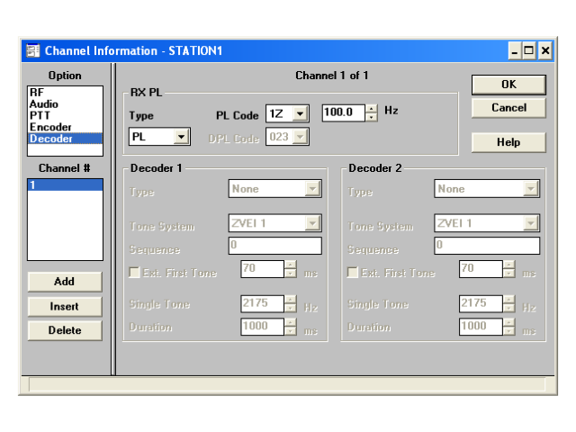
When interfacing an MTR2000 station to ANY external repeater, D-STAR, DMR, or DVM controller, make sure you’ve set the station configuration (Repeater/Base) to BASE so the station looks like a fully independent receiver and transmitter. This removes the internal repeater controller from the audio and PTT paths.
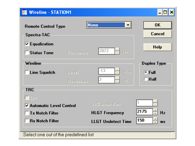
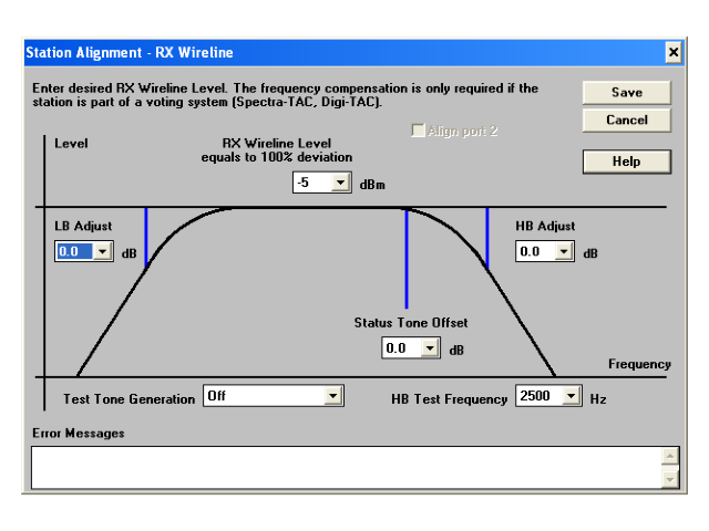
If your station has a Wireline board, make sure you set it to 4-wire even if you aren’t using it. If set to “2-wire”, the receiver audio will be muted when the transmitter is active, because the 2-wire configuration only lets one audio signal pass at a time. This is crucial when the station is configured as a “BASE” and an external repeater controller is being used.
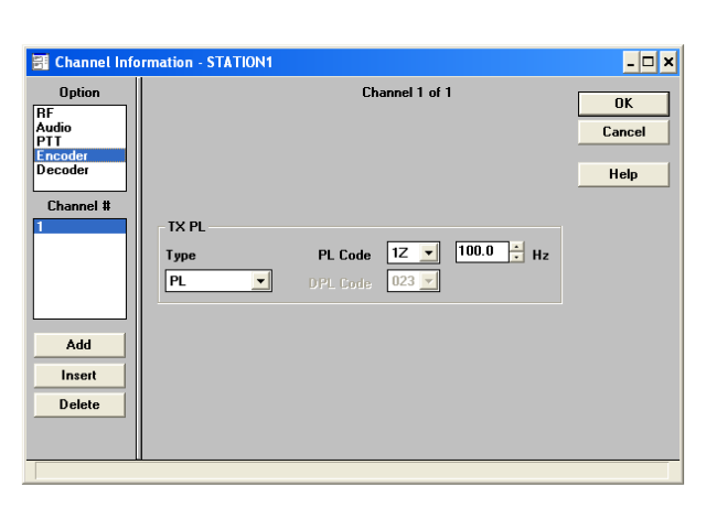
If you’re interfacing an MTR2000 station using the MRTI connector, make sure you’ve set the External PTT Mapping on the Channel Information / PTT screen to “Microphone”. When the MRTI PTT input is grounded, MRTI TX Audio replaces the front panel microphone audio as the input to the exciter.
Other Useful Notes that don’t really fit anywhere else
- The J3 Connector label is missing on the silk screen of the adapter board. This connector is immediately adjacent to J4 on the adapter board.